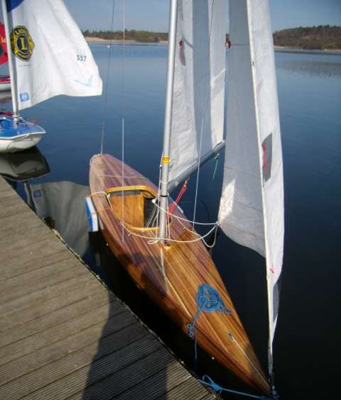
GBR82 Designed and built by Nicholas Cook.
Scroll down and enjoy the process.
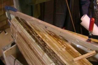
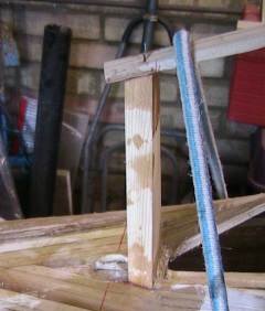
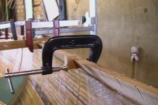
Step 3 − Keep planking until each side meets in middle of transom, then trap plank ends under a wood clamp. The ends of each strip are shaped to fit together in a herring-bone pattern.
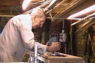
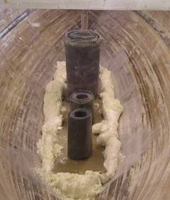
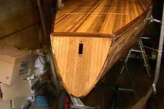
Step 6 − The hole for the rudder tube is cut using a hole-saw and the rudder post positioned.
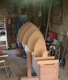
Step 1 − Set up section formers on a strong-back, making sure everything is level and aligned.
'
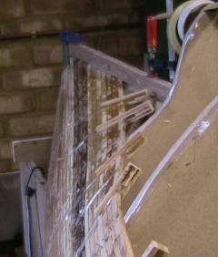
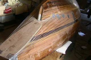
Step 4 − This is the most difficult point. The twist needed in the strips becomes too great and a hollow is developing which will need to be corrected. Sellotape strips hold the strips together. Wooden pegs, made from waste wood strip, keep the strips aligned between formers and the Sellotape keeps the epoxy off the pegs.
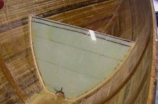
Step 5 − Eventually the twist becomes too great an it is necessary to make a join in each strip near the rudder post.
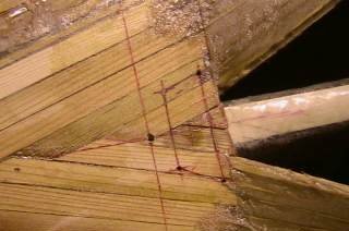
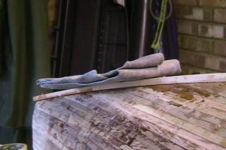
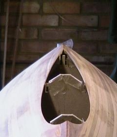
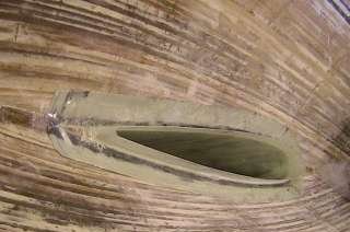
The wooden clamp has been removed to show the herring-bone joint and the positions marked for the rudder tube and post.
Step 7 − Add the first two planks that come on to the rudder post, then fill the triangular hole below these planks with short pieces, trimming the ends to butt against the hull.
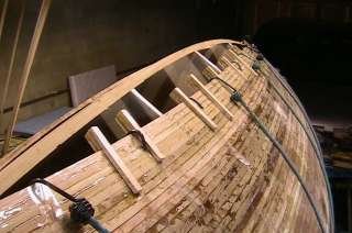
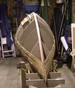
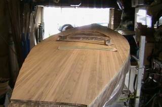
Step 8 − Continue planking until the hull is closed. There is now considerable curve in each plank and the elastic cords are needed to pull each plank hard against the previous one.
Step 9 − Plane a flat along the keel and add the outer keel band.
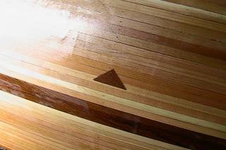
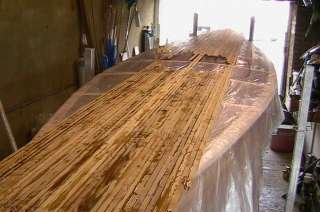
Step 10 − Now do an initial fairing of the outside surface to remove all glue runs and major steps between strips. Then run a coat of epoxy over the whole surface using a plastic spatula to force the epoxy into any crack or open joint (there should be none). Note the decorative line above the waterline, made by pre-sorting the strips into light and dark colours, and the floatation mark.
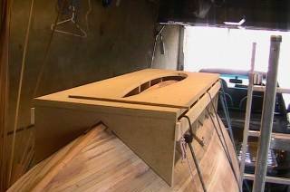
Step 11 − A router jig is strapped to the hull in the correct position to cut out the hole for the keel.
Step 12 − The hole is cut using this jig.
Step 13 − Then the jig is removed. The hull is faired again, until all the shiny epoxy is gone, sheathed using fine woven glass cloth, then lifted off the formers.
Step 14 − The formers are removed from the strong-back, the keel-hole jig is secured on the strong-back and the hull placed on it, right-way up. The hull now tends to sag open under its own weight and temporary beams are needed to hold the shearline to the correct shape. The inside surface of the hull is rough-faired to reduce steps between strips and remaining steps filled with microlite filler.
Step 15 − Now to make a start on the keel. 100mm-thick strips of polystyrene foam insulation board are cut just larger than the inside shape of the keel and glued together. These are sanded to shape of the inside of the keel using a long-board between shape formers at each end.
Step 16 − Next the rake of the keel is formed by slicing the foam off the bottom of the keel at the correct angle and gluing the cut piece to the top. A release coat is applied to the keel blank using PVC self-adhesive film, then two layers of biaxial glass cloth are laid up on the blank.
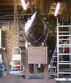
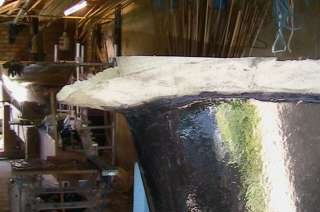
Step 17 − When properly set, the keel blank is offered up to the hull and properly aligned. A floor plate has been placed exactly 1m below the immersion point and the keel blank is sitting on this. The keel blank sticks up about 100mm into the hull.
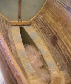
Step 18 − Expanding builder’s foam is used to mould the shape of the inside of the hull. Polyethylene sheet is used to stop the foam sticking to the hull and heavy lead weights are needed to stop the keel rising as the foam expands.
Step 19 − The keel blank is removed from the hull, a sharp wooden trailing edge added, and the keel laid up with biaxial glass cloth to its final thickness, with the cloth laid over the foam mould to make a flange which will fit against the hull.
Step 20 − The foam inside the keel is removed using a suitable cutter on a power drill (e.g. a 35mm hinge cutter) up to about 10mm from the glass in about 100mm-deep steps. The final 10mm breaks away from the PVC release film with the help of a large wood chisel. When offered back into the hull, the flange sits against the hull. The centre of the keel rises into the hull and will later form the floor of the cockpit.
Step 21 − Now, because it was built outwards from the inside, the keel needs to be faired, and this takes time and patience. Allow several days for the epoxy to harden off, otherwise the sandpaper will clog up quickly. Use a long-board to find the highest spots then work on them with a powered sander. The final fairing to shape needs to be done by hand with a long-board. Here a final layer of fine woven glass cloth has been applied using a graphite filler in the epoxy, followed by two coats of epoxy-filler applied using a roller to protect the surface for the final stages.
Step 22 − The keel is fixed into the hull: (1) by bonding the flange against the hull surface; (2) laying strips of biaxial cloth from the hull, over the flange and up the protruding part of the keel; (3) filling the “V” shaped void up to the level of the top of the keel with medium density polyurethane foam block, cut to shape, to form the cockpit floor; (4) glassing again from the hull over this floor and into the top of the keel, and (5) adding a wooden floor forward of the keel on which to step the mast.
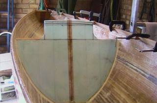
Step 23 : Now apply biaxial glass cloth to the inside surface of the hull.
Step 24 − Fabricate bulkheads from 6mm thick foam sheet, reinforced with wood where necessary and covered both sides with biaxial glass cloth. Glue these in place using epoxy and heavy-duty filleting filler.
Step 25 − Remember to leave a large drain hole in each bulkhead, as water will get in every deck-hole and needs to drain into the keel. Note the two wooden strips which, when glassed over, will form part of a ring-beam taking the stresses from the main mast stays.
Step 26 − Now a triangular-section stringer is fixed along the shearline to support the deck. Note that the stringer is sawn part through at intervals so that it bends without twisting. These cuts are filled later with epoxy filler.
Step 27 − Curved deck beams are added at intervals. These are pre-laminated from 2mm thick strip on a curved former. Note the reinforcement either side of the mast hole to support the cleats and other fittings for the mast restraint, Cunningham and whisker pole controls. The main role of the aluminium box-section strut is to hold down the ring-beam against the tensions caused by the main stays, but it also serves to support the cleats for the main and jib halyards, the centre of the control panel and the tiller (if installed).
Step 2 − Pin keel batten to tops of formers from bow to rudder post and plane to the correct angle for each former. Then start to plank up the hull from the shearline. The strips have the concave curved edge uppermost and a bead of epoxy is run along this using a 10ml syringe.
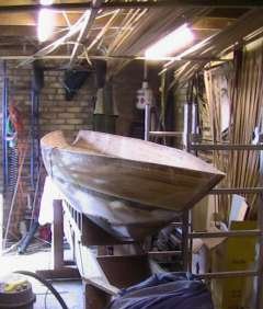
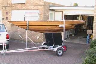
Step 28 − Now the hull has enough inherent stiffness to be put on its launching trolly.
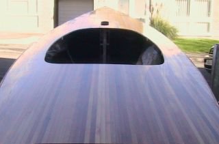
Step 29 − The deck is planked over the curved deck beams using a polyethylene sheet to prevent adhesion to the hull.
Step 30 − The top surface of the deck is faired and cut around the shearline using a router. The top surface of the deck is sheathed like the hull, then lifted off, turned upside down and sheathed inside with biaxial glass cloth.
Step 31 − Now comes a very busy time. Before the deck is finally fixed down, as much as possible of the controls need to be planned and installed. The rudder tube, bottom support flange and top support beam are installed. The permanent buoyancy is installed. The steering pedals and mast foot are installed. The stay tensioning system is installed. The main control panel is installed. The mast is stepped, the boat is sat in, ropes pulled, cleats adjusted, etcetera, until everything is just right. Once the deck is on, it is permanently on and many components are difficult or impossible to adjust later.
Step 32 − Finally the deck is fixed down. A router is run around the shearline to cut a 12mm by 12mm recess into which a hardwood quarter-round moulding is glued to give a neat gunwale. Access hatches are cut in the bow and over the rudder tube in the stern, and also the cockpit hole, all using a router and suitable jigs.
Step 33 − By using a small-diameter cutter for the rear hatch, the material cut out can be given a laminated edge and used as the hatch cover.
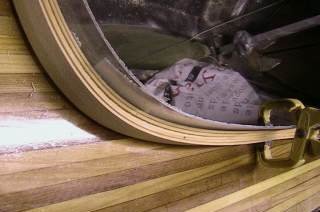
Step 34 − The cockpit edge is similarly laminated.
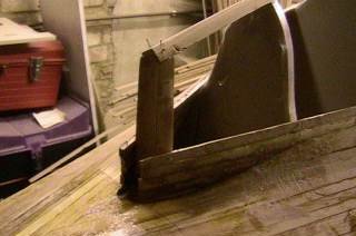
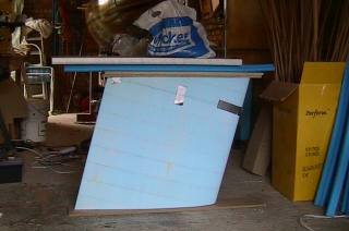
Step 35 − Now the boat is complete, except that there are hollows at the stern that do not meet class rules. This error stems from misunderstanding the definition of the term “hollows” which should have been confirmed and eliminated at the design stage. This mistake means some extra work.
Step 36 − To minimise the amount of filling required, the angle of the stern overhang was increased by cutting a new flat panel. The stretched strings are indicators for the length and depth of filling required.
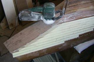
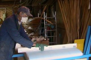
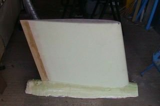
Step 37 − Strips of high density polyurethane modelling foam were epoxied to the hull and faired with a slightly curved long-board to give an indisputably legal shape.
Step 38 − The re-faired shape was sheathed with fine woven glass cloth to give the same finish as the keel.
Step 39 − A final long-boarding to a fair surface, removing much of the protective layers of epoxy, again takes time and patience. This is followed by application of a two-part varnish.
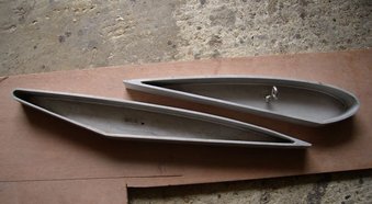
Partly because I have a friend who is an experienced pattern maker and partly because I wanted to get a good tight fit of the ballast leads in the keel, I opted to make a pair of aluminium moulds to cast split leads.
Because I contructed the keel from an inside blank, the inside is smooth and parallel. I gave the keel template to the pattern maker to make a pair of wooden patterns for casting into alumimium moulds. The patternmaker has to judge the contraction of the lead when it cools in the aluminium mould and the contraction of the aluminium when the mould is cast from the wooden pattern.
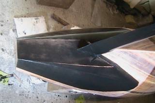
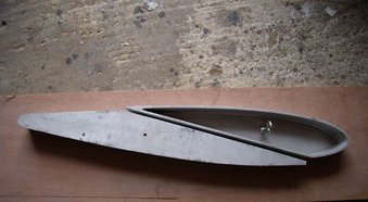
Two photos of the moulds are attached. The split is made diagonally through the centre of gravity and the widest part of the keel, so that both halves are each shorter and less wide than the space in the keel. This makes each half lead easy to lower in place and the two halves come snugly together only at the last moment. One photo shows how the two fit together, with the rear half inverted. The rear half must be cast upside down because of the rake angle of the keel. Each half is drilled and tapped M8 at its centre of gravity to take a stainless steel bolt. The lead does not stick to the aluminium or the stainless bolt, so casting leaves a threaded hole through the lead.
Casting the aluminium moulds cost £50 each. Each lead piece weighs 20kg and cost £1,10 per kilo to cast. Scrap lead costs £0,75 per kilo in the UK. The bottom pair of leads only needed running around the bottom edge with a 10mm radius router cutter to make them sit down on the base of the keel.

Step 40 − Now launch and sail your 2.4mR.