The CROss project

The CROss project

by Calle Ossiansson in his own words.

I started by downloading the free software”Freeship”, now renamed”Delftship”.

I had an idea of how the design would look like before I started. It took a while to get the picture in my mind down to the screen and be satisfied with the result.

I have some basic knowledge of boat design that my father taught me as an IOR-absorbing youngster. It’s also a good idea to read books about boat design before you start.

The software program gives you the opportunity to work with the design in a much more extensive way than what would be possible had you done it the old way with pen and razor. The major difference for an amateur is that the amount of hand calculating is reduced is reduced to almost nothing. Maybe just a few checks will be done. The program does not give hydrostatics in heeled condition though.

When you are”ready” (an illusion that never occurs) with the design and you have faired the lines its time for a printout. In Delftship you cannot deduct the skin thickness of the hull. You have two alternatives to get around this. Either you design the boat to the inside of the hull skin which is the way ships was designed in history or you do like I did. I took help from a friend who had access to a professional CAD programme where he could deduct the skin thickness and print the frames.

With the size of the Twopointfour you can print/plot the drawings in scale 1:1 which gives an upgrade in accuracy.

I roughly cut out the frames and glued them onto a board with spray glue. To cut the frames out I would have preferred a band saw but an upside down mounted jigsaw does the work as well. The better precision here the better result on the building moulds.

I built a strong box beam with some torsion stiffness. The upside was straight and not twisted. The picture is not from my garage but from a kajak project.

Then it was just to place the moulds along the centreline marked on the beam. Check the frames to be perfectly aligned or you will get in trouble later.

To endure nails in the frames and to facilitate easier dismantling of the hull from the mould, I used good old duct tape on the edges. After the alignment of the frames I secured them with a strip along the keel. This strip will stay put until I have made at least half of the freeboard.

Now its time to place the strips on the frames with a nail in each frame and glue them together. To mix the epoxi resin I used two 60ml-graded syringes without nails. You have to make a bigger hole in the base-syringe due to the viscosity of the epoxi. To get the right viscosity for gluing I mixed a filler in the resin.

The progress is slow but 13 strips on each side. To force the strips in the bow I use a clamp with a strap that could be adjusted.

When I reached the waterline it was time to set a new line for the strips. If you don’t do this the strips will edge bend too much and bring unnecessary tension into the hull. This can be done with different tools.

Now the stern is connected in the middle and the skaeg is due. Here the strips would bend too much so I cut them and stitch them together again with some fairing with a grinder. Some putty will be applied.

I place a connecting piece in the bow and the skaeg.

Starting to look good

It took a lot of ice-cream jars to mix the epoxi resin. Be sure to mix every little tiny particle of epoxy to avoid unhardened resin.

The two halves are ready. Just one piece of strip and its done.

Done!

At last the hull is put together. First chapter is concluded. Now comes the less appreciated work of grinding, puttying and fairing. I really hate that part!

The summary of this part: No bigger difficulties. The skeg was the hardest part. If you have bigger demands for a wooden look it takes more time. Use some extra control on the fairing while building. I say, use epoxi resin for gluing, if you plan to laminate the hull with epoxy. Then you know it’s strong. The number of times you plan for a new line for the strips is based upon the hulls requirements. It took about 60 hours so far. It’s crucial to have the cedar wood dried before laminating the hull. The cedar can shrink up to 3% in the direction of the fibre and only 0, 1-0, 2 % perpendicular to the fibre.

The first grinding was made with an excentergrinder connected to a vacumbuster that can endure continuous operation. It can otherwise cause a burnt vacumbuster. The next step is fairing the hull with a bendable board with grinding paper glued to it.

The grinding around the skaeg has to be done mainly by hand. The best tool to examine the result is using your hand and feels the surface. While caressing the hull one wonders is this why boats gets women’s names? 

Here’s the ready laminate-samples weighing 3,47kg/m2 without paint. The samples are very rigid. There are different methods of laminating the hull to get the right weight. I used 5,5mm thick cedar wood strips. The weight of the epoxi resin in the laminate is approximately the same as the weight of the glassfiber.

Now the boat looks like a speckled whale with all the putty and grinded surface. I asked Hasse if I could make the boat black but he recommended that I use bright colour to avoid too much heat absorbing in the sun that could cause print through i.e. you will see every glue line in the boat as the epoxy and wood behaves differently when heated. 

I have put in about 60 hours on grinding, puttying and grounding the surface. Now the

hull is laminated on the outside. Thanks to two pair of extra hands, Preben and Peter. It could be done on your own but I prefer the safer result. It took about 4 hours to complete. Afterwards, when the lamination is hardening, I add two strokes with clear epoxy on the outside to have something to fair and make ready for painting. Now the boat has to harden on the mould and I maintain the trolley instead. It needs a little attention.

I have the heater on in the garage to speed up the hardening process.

The hull is now separated from the mould. I liberated some of the frames before I had help from my wife to lift the hull over to the trolley. Next operation is to clear out the inside of the hull surface. The inside doesn’t need as much fairing as the outside. It’s enough to grind it to a pretty fair and clean surface in the area that will be visible between the bulkheads.

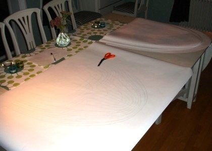
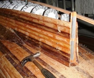
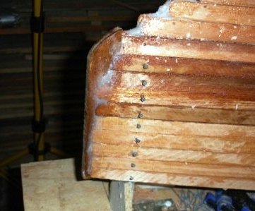
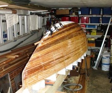
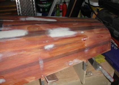
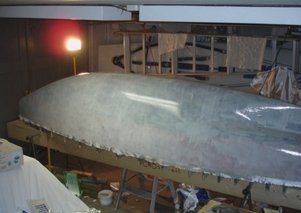
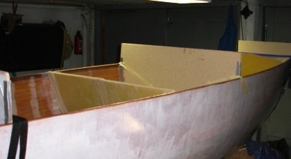
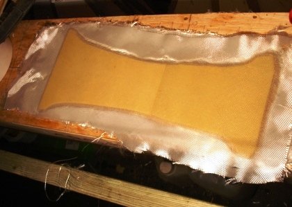
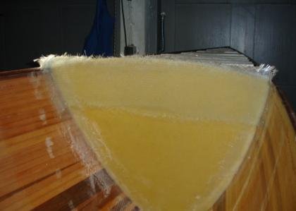
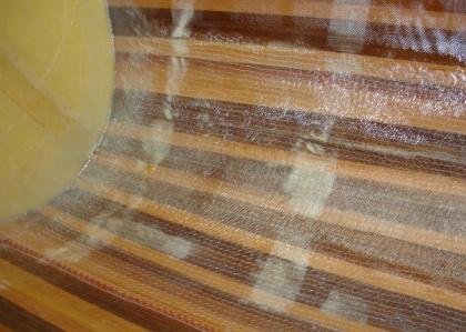
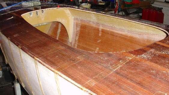
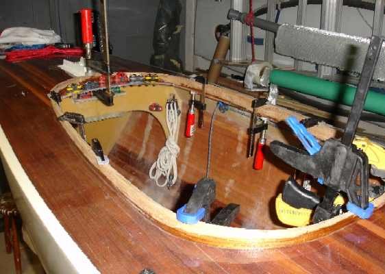
It took about 15 hours to grind the inside including puttying the holes from the nails. After a marathon race for me with the scissor, the roller and the scale, the inside is laminated as well. The flesh is tired but the spirit strong. I couldn’t go to sleep afterwards. Kept thinking of laminating, laminating and laminating. The boat is now weighed, 17-17, 5 kg, which is perfect with the desired weight. The hull shall now weigh approx 5, 2m*3, 6kg/m2=18,7kg. If the calculations are accurate the lead-weight in the keel is considerable.

I put a “sheer strake” inside the sheer line to support the deck. When you laminate thin weave cloth around edges, align the fibres in a diagonal direction to the edge. The fibre doesn’t have to bend that hard and you are likely getting a better result with less air bubbles. You can also put in some “filler” to make the resin more sticky.

Laminated the main bulkheads with Airex foam core. Consider the amount of resin to prime for lamination (approx. 300g/m2), when you decide upon the thickness of the foam core.

Is this the Holy Grail or is it a rudder shaft-casing, with the bearing. After a little search for tubing with the right dimension I laminated this “thing”. It’s a good idea to wax the tubing carefully to avoid hours of freeing the tubes from the laminate.

In the effort of saving some work time I used Hasse´s original Norlin MK III moulds for the keel. I used six layers of 450g cloth and two layers of 160g cloth surrounding the heavier cloth. You get a smoother surface and less need for putty.

A good preparation for connecting the two halves is not to use the full thickness of all layers around the edges of the halves. As they should be laminated together there would be layers added over the joint to cover for that. Make careful grinding to prepare the laminating. There would be very little work needed on the outside. The aft edges are joined by epoxy resin with “filler” in it. The bottom and the front edge are laminated with pre-wetted laminate, lifted in place with two sticks with nails in the ends.

Now I laminate the two main bulkheads into the hull. To assure me of the unaltered shape of the hull I have some frames secured in the hull. Here you could check the alignment of the hull again. This is the last time to avoid any deviations from your design.

The floatation foam is fitted. The volume of the foam can be checked by comparing the density of the foam with the weight of the fitted foam. It’s not a hundred percent accurate but will fill the needs. The boats tends to have a shortage of lift in the bow, therefore a check is important. When calculating the floatation ability of the boat one should consider the hull, internal bulkheads and even the volume of the lead. That is compared with the total weight of the boat including the ballast of 35kg.

While waiting for the mould wax for the making of lead moulds there are lots of other things to do. Making of the rudder quadrant and installation in the rear compartment. The tubing is ordinary plastic tubes that electricians use in walls. I want to keep the rear flotation free from saltwater and moisture. The hatch for the rudder installation is to be watertight.

The aft deck/transom is glued in one stage. The learning from this will be used when laying the deck. A plastic sheet is used to cover the interior from being dirty. The only trouble with this area is that the surface is bent in two directions, therefore the use of straps.

The last foam core is laminated. This part is intended for a mid vertical beam to take care of load of the keel.

The diagonals for super structuring the cockpit area is laminated.

There should be enough space for my shoulders while the diagonals are reduced in size at the rear bulkhead.

The fastener for the shrouds will be along the diagonals upper side. This will give at static, rigid point of the hull for good transfer of forces from the rigging.

The mast is pivoted in the mast column hole. This gives heavy loads on the structure at this point. Therefore I reinforce the mast bulkhead with some extra laminate.

I also laminate an extra layer in the bottom with a 450g cloth of biaxial fibre.

The plug for making lead moulds is made of mould wax. It’s heated and poured into the keel. The cold wax could then be pulled out with some carefulness. If the wax breaks it could be warmed together again. When moulding the second layer approx. 10cm from the bottom, I use wet sand in the keel, well flattened.

You’ll need supportive tubing in the wax to stabilize the plug when pulling it out. Then put some rope or handles onto it to use when lifting. Then the plug is used in a tube of concrete with some reinforcements due to the high temperature.

The rudder shaped out of Cedarwood, primed and the stock mounted with 3 big screws. Next is sheating with 160gr/m2 glass and epoxy and some extra around the stock.

Maximum thickness of the rudder is 38mm and NACA 0013 profile should render a safe rudder with low resistance. The rudder will be hung in the bottom end. Final weight will be around 1400g, a bit overweight compared to a balsa rudder that would have been under 1000g.

The structure around the mast/rig/keel in place. The center beam is going domn into the keel and will keep the keel loocked. The bulkhead in front is a temporary templet for the deckcurve.

It was a full days work to get the deck glued. All that is left of the cedarwood I bought is half a length, feels good. I had the strips tejped together on the underside in portions, then it was easy to open the gluelines and get the resin down. The whole package was held together with maskingtejp and a couple of clamps.

Pouring lead.

The deck sheated on the top. I have put on some extra epoxiy wet on wet on top of the glass to not sand into the glassfibre as I plan to leave the deck clear.

198kg of lead with a snug fit. If my calculations are right this is the amount that she will float. Before processing the leadbars I was 20kg overweight. Measurin how well the leadbars fit is done by checking how much water can be pourd down till the water reaches the top of the lead. SWE 364 is down on 1,1L this ones 1,6L, good enough. Now its time to fit the keel to the hull, a time for accuracy and check back. 

The keel is fixed and next it will be laminated to the hull. Lots of anxiety and checking before final decision.

Rolled out in the cradle for the first time, hands for Calle.

Checking floatation trim/displacement in the measurement tank. Reality versus calculation, result OK.

The deck is finally glued in place.

After some evaluation I decided to make my own design on the cockpit coaming. I made a templet to glue the veneers onto after treating it with tape and mould release. I cut some 1mm teak on my own circular saw and made use of all available clamps.

Ready for fitting out. Will it be ready for WC in august.

Ball bearings for the rudder are common stuff among bigger racing yachts. I built my bearings from blocks.

First taste of saltwater. Fitting out was more time-consuming than expected but that’s the way it is when you are trying out new solutions.

Shakedown time!

Happiness is a warm gun!

I could not hold myself back from taking the new boat to WC in Denmark though I had only sailed her a couple of hours.

Everything worked ok during the regatta apart from a rudder failure. I had to be towed in and lost the second race but managed to get out 10 minutes in advance of the third race.

Naturally there are details that need adjustment. I ended up as no. 35 which feels ok taken the little time for preparation in account.

Wintertraining outside Långedrag.


Epilog 

A project like this does not end until the boat is sold, the drawings are burnt and your memory is lost.

Apart from that a little summing up feels appropriate at this stage. My aim with the project was to satisfy my eager to be creative and prove to myself and the 2,4 community that a project like this can be accomplished on a hobby basis without any professional expensive tooling. I set myself up to build as much of it with my own hands as possible.

You can buy more or less finished parts depending on your own preferences and there are as many ways to pursue a project like this as there are builders. I have used 700 hours all in all and most of them have been very pleasing. Sometimes “Murphy” has been around to make things difficult but that is part of it.’

The boat was built in a double garage with one car inside all the time so I had 2,5mx5m as working area but a little more space to swing the longer strips around so I had the project close which is important in my mind.  My total budget has been 40.000 SEK and that does not include sails and cradle. Rig and fittings are the most expensive parts.

It is very satisfying to work out your own solutions to different problems or develop new variations to known solutions. I have no skills in boatbuilding on before hand but I have been a sailor and boat owner as long as I can remember. The best advice I can give anybody who is prone to start building a boat is don’t be afraid to ask skilled people for advice.

When you enter an endeavour like this you hope to build a competitive boat and you are eager to see some fast results. The first regatta I sailed was the WC which maybe isn’t the smartest shake down regatta to choose. I am pretty confident I would have done better with my old boat but it takes time to get to know a new boat and get the maximum out of her, not even the Norlin Mk III was a winner the first years of its appearance.

During the autumn I have improved performance and I have also achieved my first regatta win with the boat, the prestigious Fleet Championship regatta.